These adapters output a 0 12 v pulsed speed signal that matches the frequency of the signal produced by a magnetic vr inductive sensor or two wire hall effect sensor.
Hall effect sensor voltage converter.
Connecting magnetic vr inductive sensors and two wire hall effect sensors to the cortex ebc will require the use of a speed sensor adapter.
Hall effect sensor check the power supply to the sensor.
Its operation relies on the hall effect shown in figure 1 a where current i flowing through a conductor in the presence of an applied magnetic field b generates a transverse hall voltage u h that is a function of the current the magnetic field the thickness.
1 if the drive current in an open loop system is controlled using a constant current source and the differential hall voltage is amplified an output voltage proportional to the primary current only.
The drv5055 is a linear hall effect sensor that responds proportionally to magnetic flux density.
Model 4028 frequency to voltage converters changes the frequency output of any magnetic speed sensor or hall effect speed sensor into a proportional 0 10v or 0 5v output signal.
It was discovered by edwin hall in 1879.
Hall effect sensors are the most common type of magnetic current sensor.
6 is another type of digital on off sensing device.
Power inputs can be configured for either a 2 wire or 3 wire power supply.
This cycle is repeated to create the digital signal from the shielded field hall effect sensor.
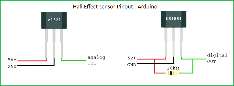
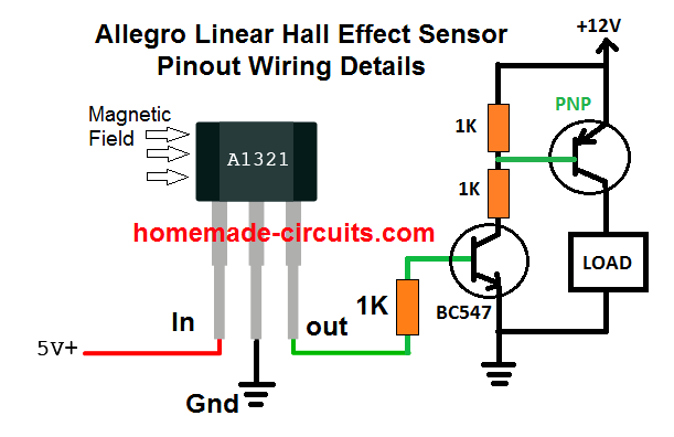
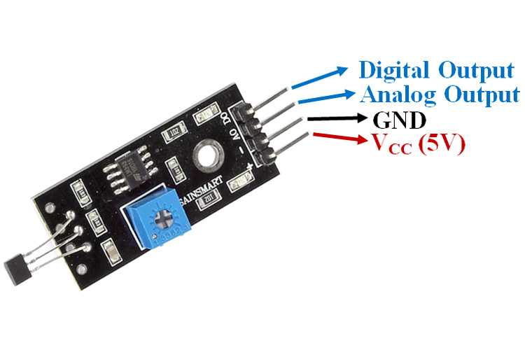
The usual supplying voltage is 5 v in some cases can be 12 v.
Thus the signal voltage drops very close to ground.
The circuit is turned on which completes the ground leg from the load.
Spectec s signal converters match an array of digital hall effect active magnetic speed sensors or passive magnetic speed sensors and operate in environments with a wide temperature range.
The hall effect is the production of a voltage difference the hall voltage across an electrical conductor transverse to an electric current in the conductor and to an applied magnetic field perpendicular to the current.
The device can be used for accurate position sensing in a wide range of applications.
As current flows in the conductor the toroid concentrates the resulting magnetic field through the standard single in line package sip.
Compactly fits an explosion proof elby 50 or 75 enclosure.
Illustration of the basic principle and structure of the hall effect open loop current sensor.
The device operates from 3 3 v or 5 v power supplies.
Also this operation can be performed and when the connector of the sensor is plugged in.
The gear tooth hall effect sensor fig.
The a1360 linear hall effect sensor is typically placed in the gap of a ferromagnetic toroid which surrounds each inverter phase conductor in the motor figure 2.
Check the size of the air gap g between the sensor and the trigger wheel g 0 8 1 5 mm 0 03 0 06 inch.
Model 4026 as freq to voltage signal converter can be configured with 0 5 v or 0 10 v ftv output.