Before cable gland assembly or stripping of the cable gland assembly consideration should be given to any cable gland accessories that may be required such as.
Hawke cable gland installation manual.
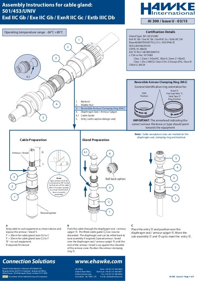
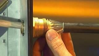
Braid x flat steel wire y steel tape z ring position swa position general identification ring orientation for.
Hawke is the market leading manufacturer of exd exe cable glands and connection solutions.
To download and store an electronic version of a particular instruction guide please use the links below.
5mm minimum recommended 6 2 1 6 3 2 1 4 1 2 5 6 accessories.
Assembly of glands using 2122 can be completed prior to the compound reaching a fully cured state.
Discover our products including enclosures connectors and controls.
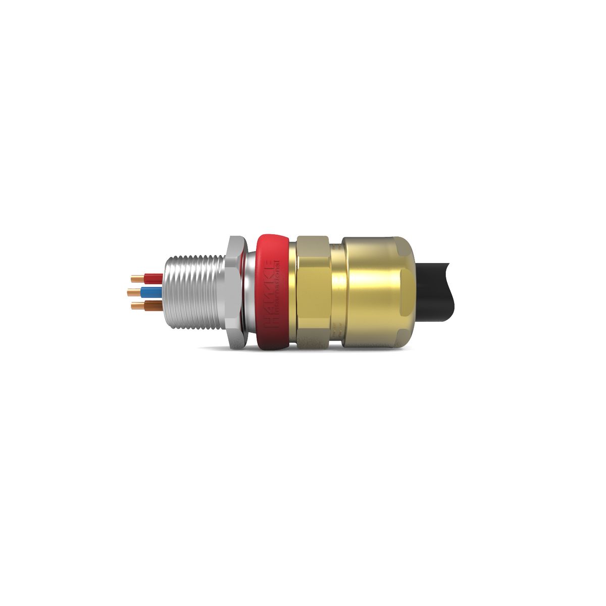
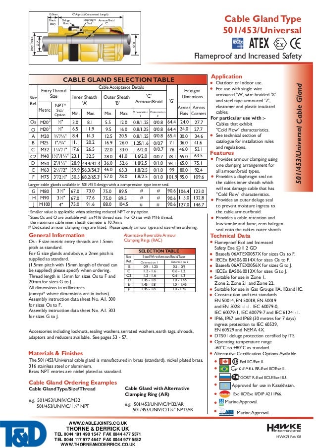
The 501 453 universal cable gland is dual certified exe exd robust and for use with single wire armour w wire braid x steel tape armour z elastomer and plastic insulated cables.
The arrowhead indicating the correct armour thickness or type should point towards the equipment i note.
Gland assembly see graphs.
If required fit shroud over the cable outer sheath prepare the cable by removing the cable outer sheath and the armour to suit the geometry of the equipment.
Pre fitted cable guide can now be discarded.
Hawke cable glands all hawke international cable glands meet and in most cases exceed the test requirements for products used in potentially hazardous areas.
Continue gland installation gland installation can now continue as per the gland assembly instructions.
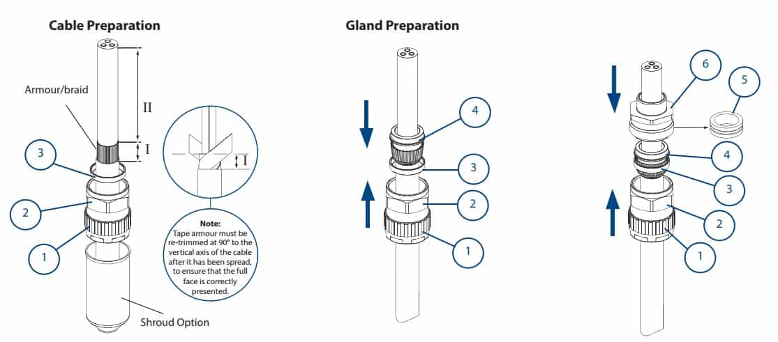
I 20mm for cable gland sizes os to c i 25mm for cable gland sizes c2 to f ii to suit equipment.
Tape armour must be re trimmed at 90 to the vertical axis of.
With over 60 years of experience manufacturing cable termination products for the most arduous environments and a reputation built off safety and reliability hawke.
For particular use with cables that exhibit cold flow characteristics.
Gland preparation a strip cable to suit equipment as shown above and expose the armour braid i.
Reversible armour clamping ring rac important.
If required fit shroud b push the cable through the diaphragm seal armour spigot.
Remove a further 18mm maximum 3.
For remote installation please read all instructions carefully before beginning the installation installation instructions for cable gland type cx 1.
Installation instructions full installation guides are available for our full product range and these are included with product shipments.
If m16 entry is used on o size cable glands the maximum cable inner sheath diameter is limited to 10 9mm.